
Case Study: From Existing Part to Production Tooling
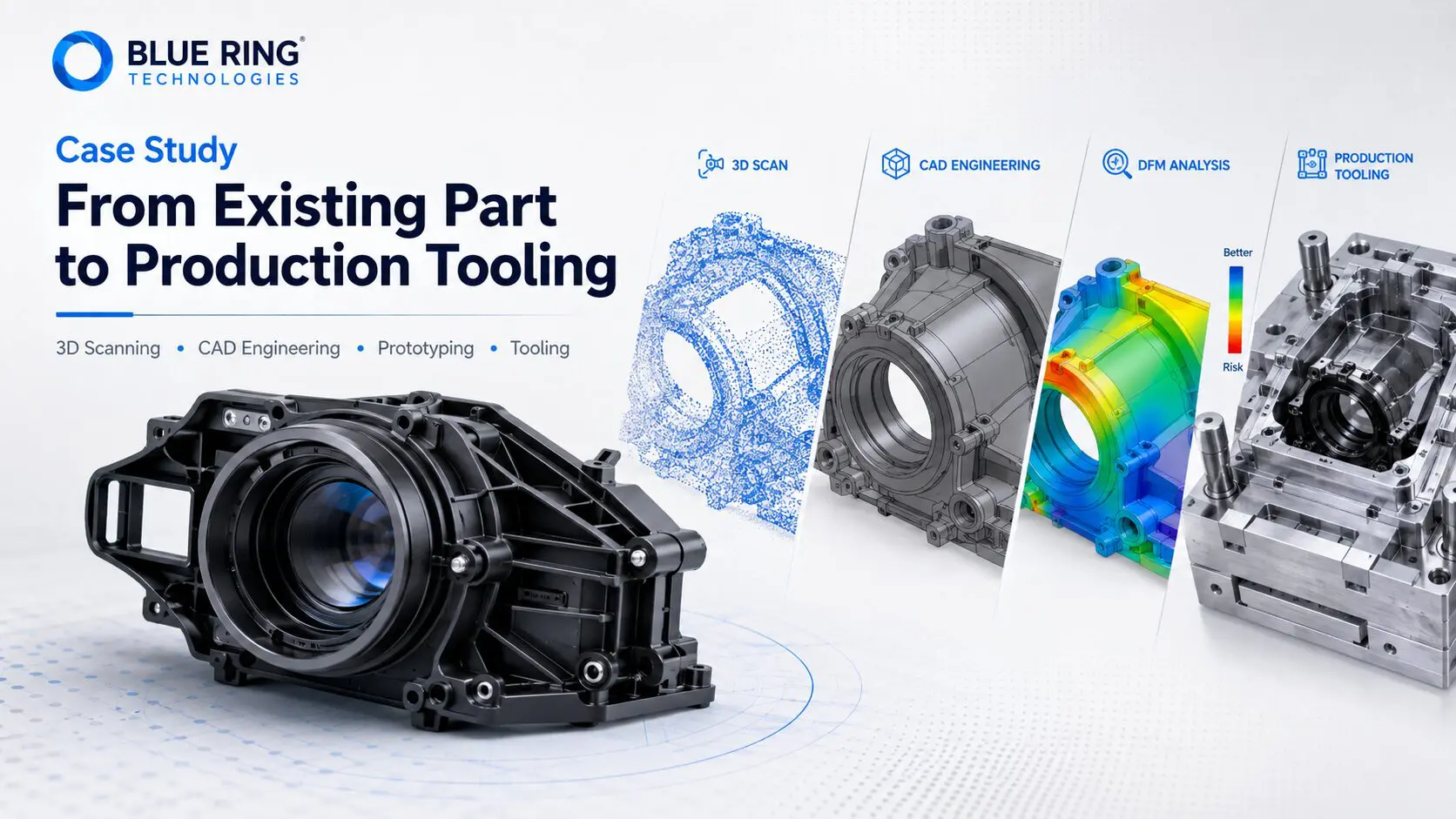
How Blue Ring Technologies Used 3D Scanning, Reverse Engineering, Prototyping, and DFM to Prepare a Complex Plastic Component for Production
A customer approached Blue Ring Technologies with an existing molded plastic component that needed to be recreated, modified, and prepared for reliable injection molding.
The component included complex curved geometry, precision mounting features, critical cosmetic surfaces, and a highly polished finish. Producing the new component required much more than simply duplicating the original part.
Blue Ring Technologies developed the project through a structured engineering process:
Original Part Evaluation → 3D Scanning → CAD Engineering → 3D Printed Prototype → Design for Manufacturing → Mold Engineering → Tool Manufacturing → T1 Validation → Production
The project demonstrates how combining reverse engineering, prototyping, and injection molding expertise can significantly reduce development and tooling risk.
Phase 1 – Original Part Evaluation
The project began with a detailed engineering evaluation of the customer’s existing component.
Blue Ring reviewed:
- Overall geometry
- Critical dimensions
- Mounting interfaces
- Structural features
- Cosmetic surfaces
- Material characteristics
- Assembly requirements
One of the most important considerations was the component’s highly polished cosmetic surface.
Because appearance and surface quality were critical to the finished product, those requirements needed to be considered throughout the entire engineering and tooling process.
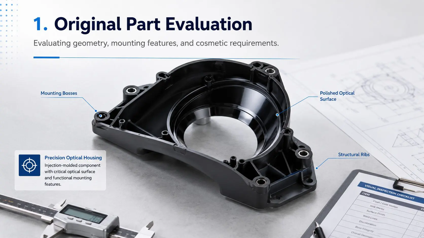
Original Part Evaluation
Phase 2 – High-Resolution 3D Scanning
The component contained complex surfaces that would have been difficult to accurately reproduce using manual measurements alone.
Blue Ring Technologies used high-resolution 3D scanning to digitally capture the existing component.
Multiple scans were combined to create a dense digital representation of the part geometry.
The resulting scan data provided an accurate foundation for reverse engineering and CAD development.
Benefits of 3D Scanning
- Captures complex surfaces
- Preserves critical geometry
- Reduces manual measurement errors
- Accelerates reverse engineering
- Provides a digital reference for CAD validation
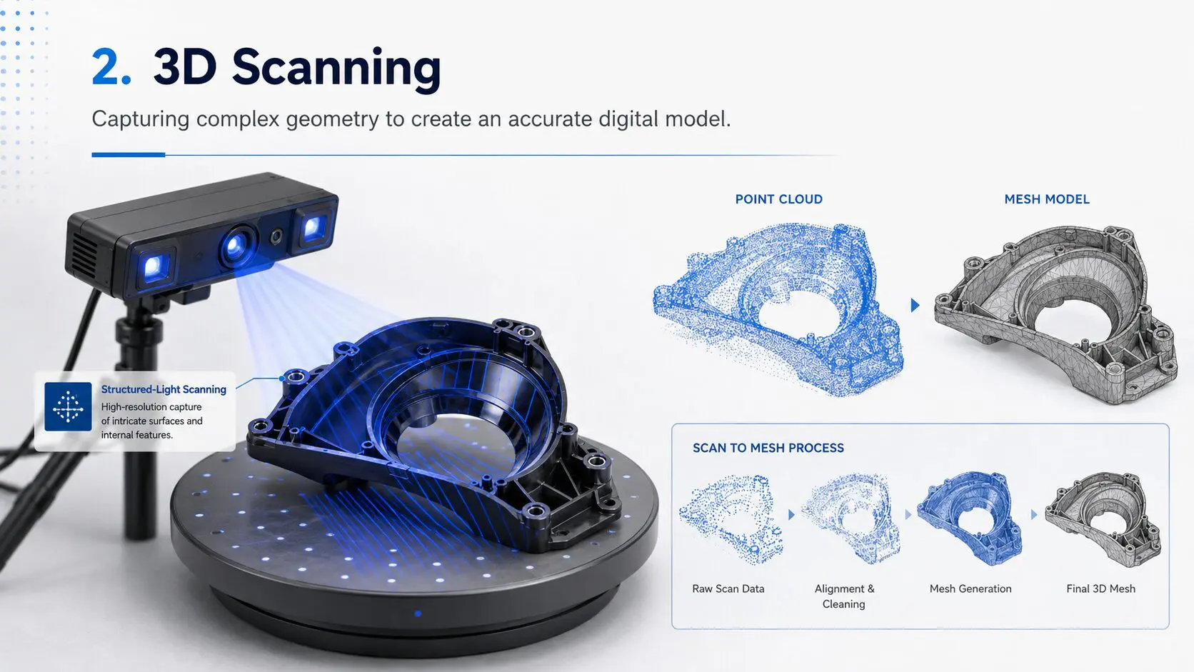
3D Scanning Workflow
Phase 3 – CAD Engineering
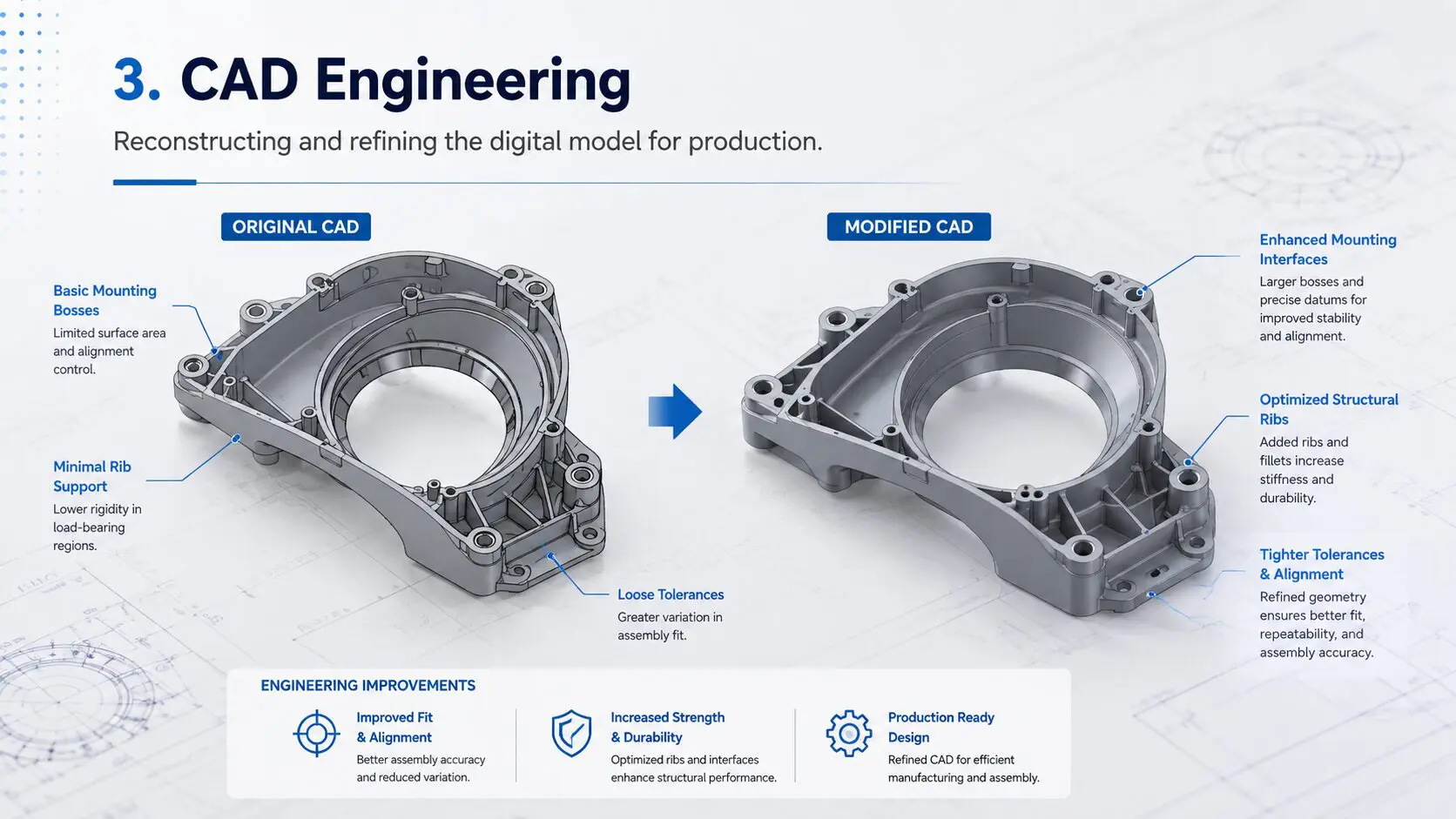
Once the scan data was completed, Blue Ring reconstructed the component as a fully engineered CAD model.
The objective was not simply to duplicate the existing geometry.
The new CAD model needed to support:
- Engineering modifications
- Assembly verification
- Design revisions
- DFM analysis
- Mold design
- Future production changes
During this phase, mounting and interface geometry was refined to improve alignment with the mating assembly while maintaining the original functional intent.
Phase 4 – 3D Printed Prototype Validation
Before production tooling was manufactured, Blue Ring Technologies produced a functional 3D printed prototype.
The prototype allowed the engineering team to physically verify:
- Overall geometry
- Mounting locations
- Assembly fit
- Interface alignment
- Structural features
- Design intent
This provided an opportunity to identify potential issues before committing to production tooling.
Changes to a CAD model or prototype are relatively inexpensive.
Changes to a completed injection mold can be significantly more costly.
Prototype validation therefore provides an important layer of risk reduction before steel is cut.
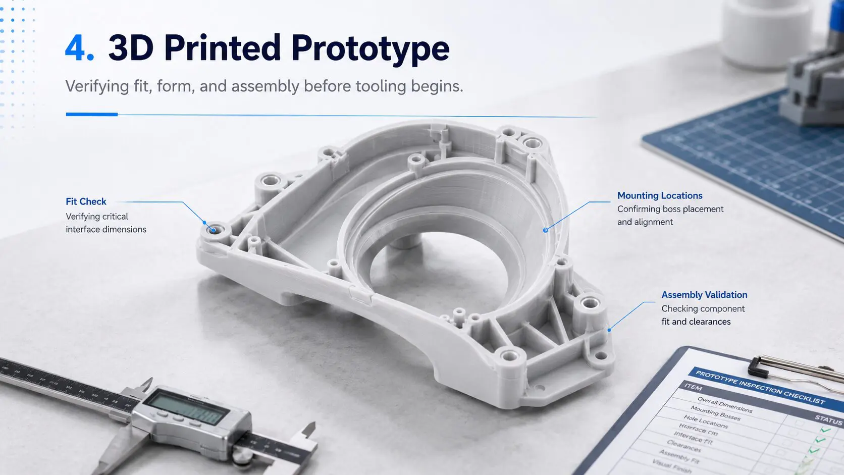
Functional Prototype Used for Fit, Form, and Assembly Validation
Phase 5 – Design for Manufacturing
Following prototype validation, Blue Ring performed a comprehensive Design for Manufacturing (DFM) review.
The objective was to determine how the component would behave during injection molding and identify potential manufacturing risks before mold construction.
The DFM review included:
- Mold layout
- Injection system
- Gate locations
- Parting lines
- Draft angles
- Wall thickness
- Ejection strategy
- Venting
- Cooling
- Surface finish
- Mold inserts
Draft Angle Optimization
Several areas of the geometry required adjustment to provide proper mold release.
Small engineering modifications were introduced to improve draft while maintaining the functional requirements of the component.
Proper draft helps:
- Improve part release
- Reduce ejection force
- Reduce tooling wear
- Minimize cosmetic damage
- Improve production consistency
Wall Thickness Analysis
Wall thickness was evaluated to identify localized areas that could potentially create:
- Sink marks
- Warpage
- Uneven cooling
- Dimensional variation
These conditions were reviewed before mold manufacturing so potential problems could be addressed early in the development process.
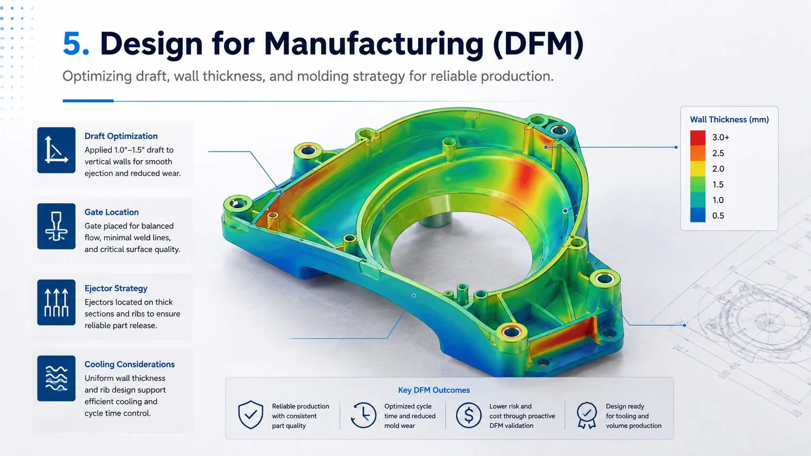
Wall Thickness Analysis
Phase 6 – Mold Design & Tool Engineering
Once the DFM review was completed, Blue Ring Technologies engineered the production injection mold.
The tooling incorporated:
- Multi-cavity mold layout
- Engineered runner system
- Optimized gate locations
- Precision mold inserts
- Cooling circuits
- Ejection system
- Mold venting
- High-polish cosmetic surfaces
Every major tool design decision was evaluated for production reliability, part quality, and long-term maintainability.
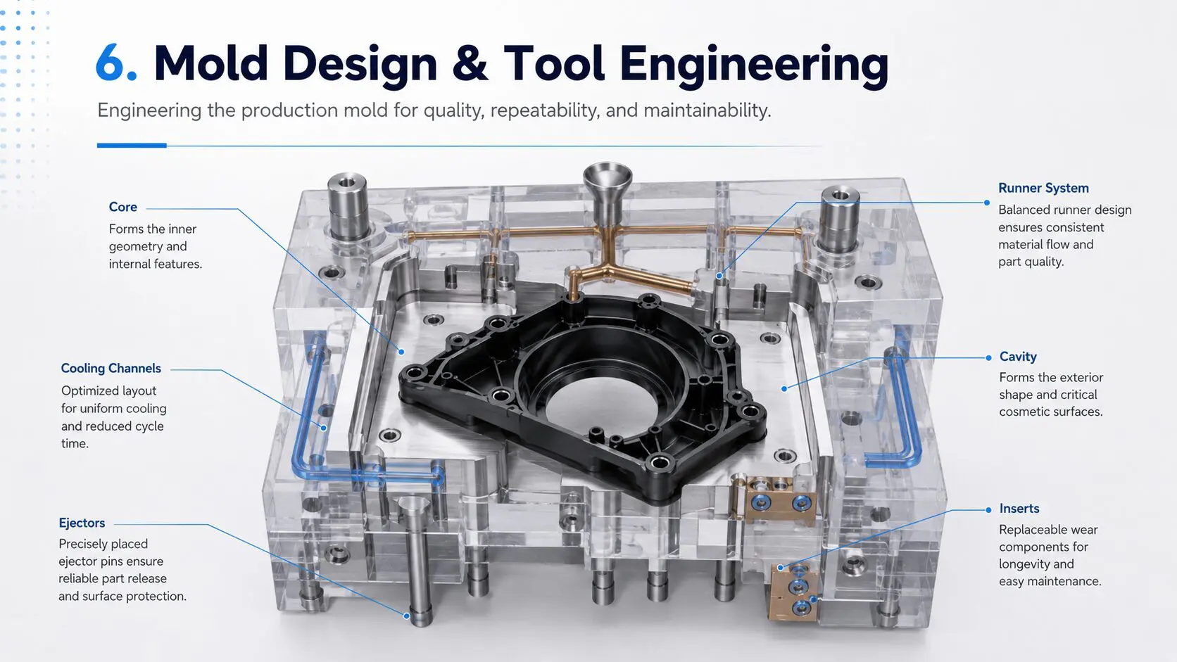
Production Mold Engineering
Phase 7 – Tool Manufacturing
After engineering approval, the project transitioned into tool manufacturing.
The production mold progressed through:
- Mold base preparation
- CNC machining
- Core and cavity manufacturing
- EDM
- Wire EDM
- Insert manufacturing
- Precision polishing
- Parting-line fitting
- Mold assembly
Throughout the process, dimensional and manufacturing inspections were performed before the mold advanced to the next stage.
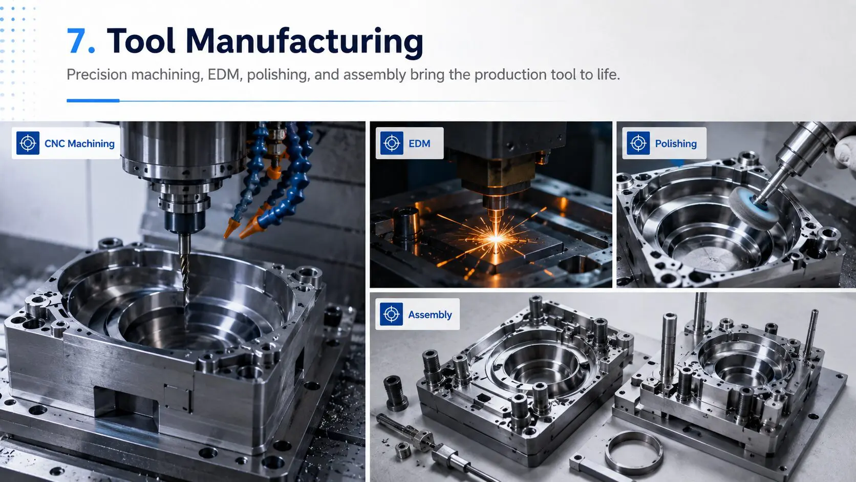
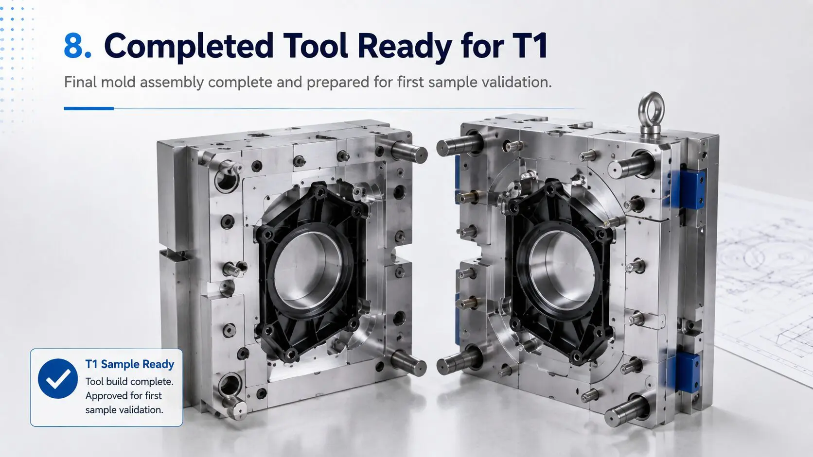
Phase 8 – T1 Sampling
Once mold construction is completed, the next major milestone is T1 sampling.
T1 represents the first molding trial using the completed production tool.
During the trial, Blue Ring evaluates:
- Mold filling
- Part dimensions
- Surface quality
- Gate performance
- Ejection
- Flash
- Sink marks
- Warpage
- Assembly fit
- Overall appearance
Results from T1 are used to determine whether any final tooling or process adjustments are required before production release.
Why This Process Matters
This project demonstrates that successful injection molding begins long before parts start coming out of a molding machine.
Blue Ring Technologies combined:
3D Scanning
Reverse Engineering
CAD Engineering
3D Printed Prototyping
Design for Manufacturing
Mold Engineering
Tool Manufacturing
into one controlled development process.
Each phase reduced uncertainty before the project moved into the next stage.
Starting With an Existing Part
Companies do not always need complete production drawings or perfect CAD files to begin an injection molding project.
Blue Ring Technologies can often begin with an existing physical component.
From there, our engineering team can help:
- Evaluate the existing product
- 3D scan the component
- Reverse engineer the geometry
- Develop production CAD
- Modify the design
- Produce functional prototypes
- Perform DFM analysis
- Engineer production tooling
- Manufacture injection molds
- Produce finished plastic components
This project is one example of how Blue Ring Technologies helps customers move from an existing physical product to a controlled, production-ready manufacturing process.
Have an Existing Plastic Part You Need to Manufacture?
Whether you have an existing component, CAD files, an old mold, or a prototype, Blue Ring Technologies can help determine the best path toward production.
Blue Ring Technologies
Engineering First. Tooling Second. Production Always in Mind.
Contact Us: support@blueringtechnologies.com